This article introduces a method for quantifying the reliability of grounding conductors for the design of substations and other high voltage electrical applications. The method uses the standard reliability formula and normal continuous probabilities (bell curves) for the distribution of field failures over time. Reliability is then calculated by estimating the probability of missing grounding conductors from breaks, loosening joints, theft, and wind fatigue. The results suggest that Copperweld is 17% more reliable than copper, given a 30-year service life, and can help drive power grid resiliency by extending service life.
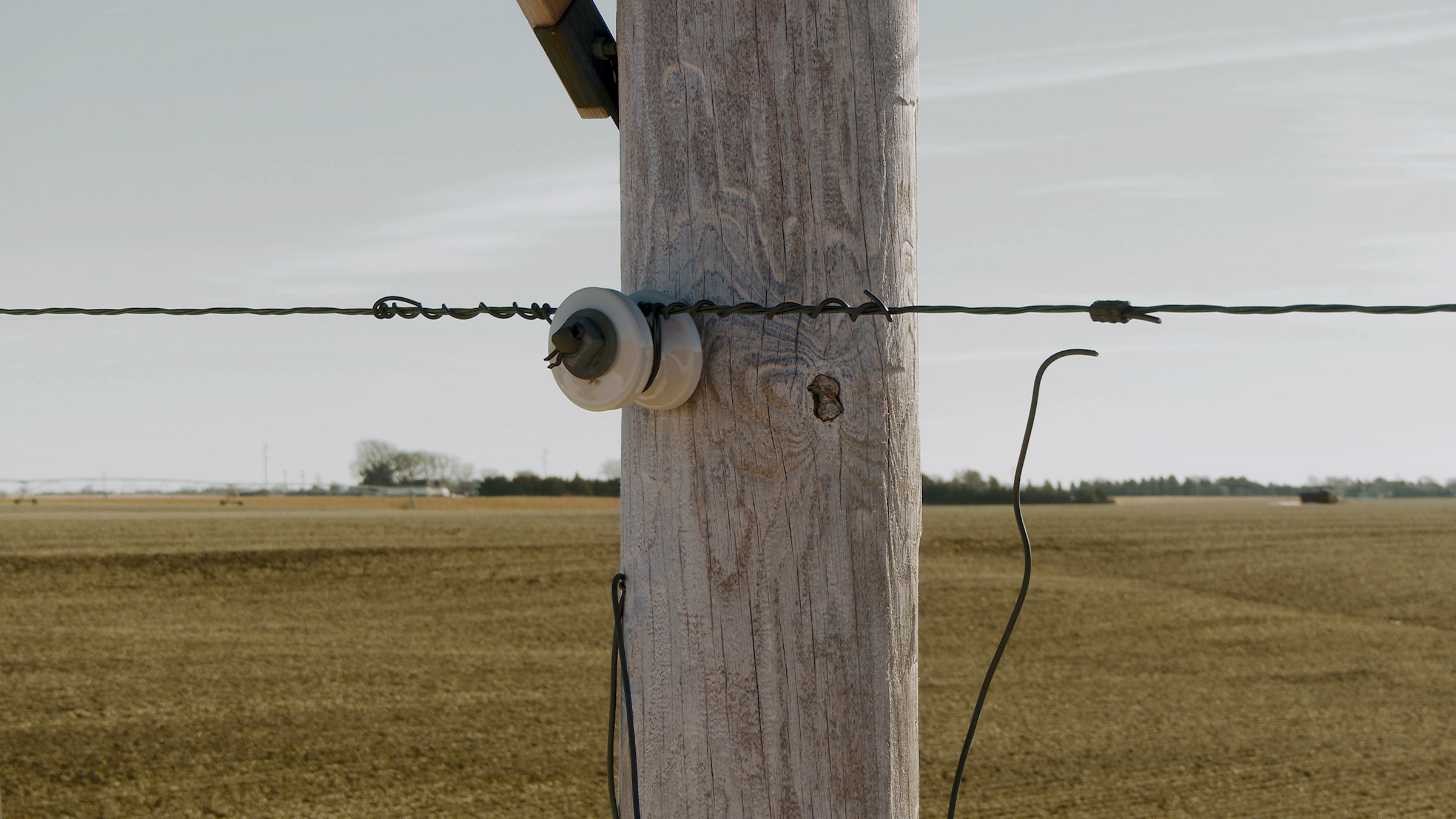
Contemporary models for grounding conductor selection are based on the conductivity and short circuit ampacity performance at installation and not on the likelihood of the conductor being in place when a fault is likely to occur years—or often decades—later. Often, the protective ground circuit that conducts short circuit fault currents safely into the ground is found broken or missing in some parts of the power grid as a result of weather-induced aging. One example of a fault resulting from a broken pole ground in a remote region of Nebraska is provided by ATV footage at the overhead neutral (Figure 1).
Figure 1. Broken copper pole ground at the overhead neutral (Nebraska 2019)
IEEE provides Guidelines for Safety in AC Substation Grounding (Std 80) to select grounding conductors on the basis of electrical conductivity, corrosion resistance, current carrying capacity, and mechanical strength. However, of the twelve pages devoted to selection criteria, ten pages are dedicated to current carrying capacity. Only one page describes mechanical strength and corrosion considerations. Although Std 80 implies that reliability is a basic requirement for grounding selection, it does not provide guidance on how to quantify it. Considerations for reliability are qualitative and subjective. As a result, the service life of the protective circuit is not seriously a consideration in the standard, leaving design engineers without counsel. And so, the focus on relative conductivity and theoretical current carrying capability of various conductors, without consideration of reliability, favors the selection of copper.
Estimating and quantifying the likelihood of a conductor’s failure over the expected design life is critical to the selection criteria. Mechanical reliability, corrosion resistance (specifically galvanic corrosion), and theft deterrence must be evaluated. In fact, Std 80 verifies that reliability is critical by stating in the preamble of the selection criteria section that “…proper selection of conductor material will maintain the integrity of a grounding system for years.” 1
Design engineers need a reliability model to complement their relative fusing-resistance ampacity model. This paper introduces a new method for selecting conductors in any grounding application based on a reliability factor. The new method is intended to help design engineers determine if their IEEE-compliant grounding conductor will conduct a short circuit fault to ground throughout the entirety of its service life.
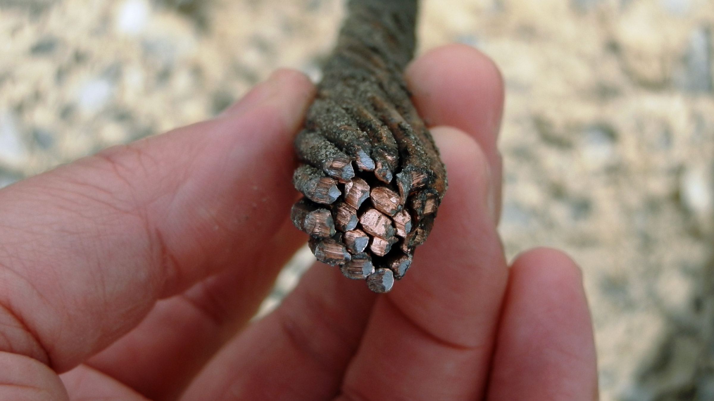
Copperweld CCS was used in applications ranging from telephone communication wiring to grounding conductors from the early 1900s through the 1960s. In rural communities, CCS was used as a power conductor to electrify farms. For example, we have confirmed over 100 sites in Kearney, Nebraska presently in use today that were installed in 1946 to power aqueduct irrigation pumps on farms—73 years after installation.
To better understand the applicability of CCS in non-steady-state grounding current applications, Copperweld Bimetallics, then called Copperweld Steel Company of Pittsburg, began testing its own products to find the fusing limit in 1971. Publication of test results and practical grounding guides drove sales of CCS. By the end of the 1970s, CCS was used in buried grounding applications such as ground grid conductors at substations, as well as exposed grounding applications in power distribution poles and substation equipment.2, 3, 4
In 1981, a new universal formula was approved in IEEE Std 80 for relative prediction of fusing-resistance of various grounding conductors. It was carefully calibrated to the performance of copper, and it provided factors for the relative performance of other grounding conductor solutions. In the years that followed, CCS became known as a solution only for high-theft areas, particularly at street level and visible locations.5
Interestingly, and critical to the reliability findings of this paper, CCS grounding solutions installed in the 1970s remain in place throughout the Power Grid in both buried and above-grade applications based on user findings.
The most commonly used function in reliability engineering is the reliability function, R(t). This function determines the probability of success in terms of the unreliability function, Q(t), which is the probability of failure over a period of time, ‘t’.
We are aware that some utilities want their grounding installation to last 50 years. In the case of grounding conductor selection, we have assumed a reasonable minimum service life for a grounding conductor to be 30 years. Since reliability and unreliability are the probabilities of these two mutually exclusive states, the sum of these probabilities is equal to 1. That is,
R(t) = Q(t) = 1
Therefore, the reliability R(t) over the period of the expected service life can be expressed as follows:
R(t) = 1 - Q(t)
Where, t = 30 years
Over this range, the probability of conductor failure ranges from installation to decades later. Assuming the rate of failure of any given conductor can be expressed as a continuous random variable with a normal probability distribution, or in other words a bell curve, a time can be established somewhere in that service life as the threshold between success and failure, as shown in Figure 2.5 We have used this relationship to estimate the probabilistic service life of a hypothetical grounding conductor over time. A visualization of this relationship is expressed by the graph shown in Figure 2.
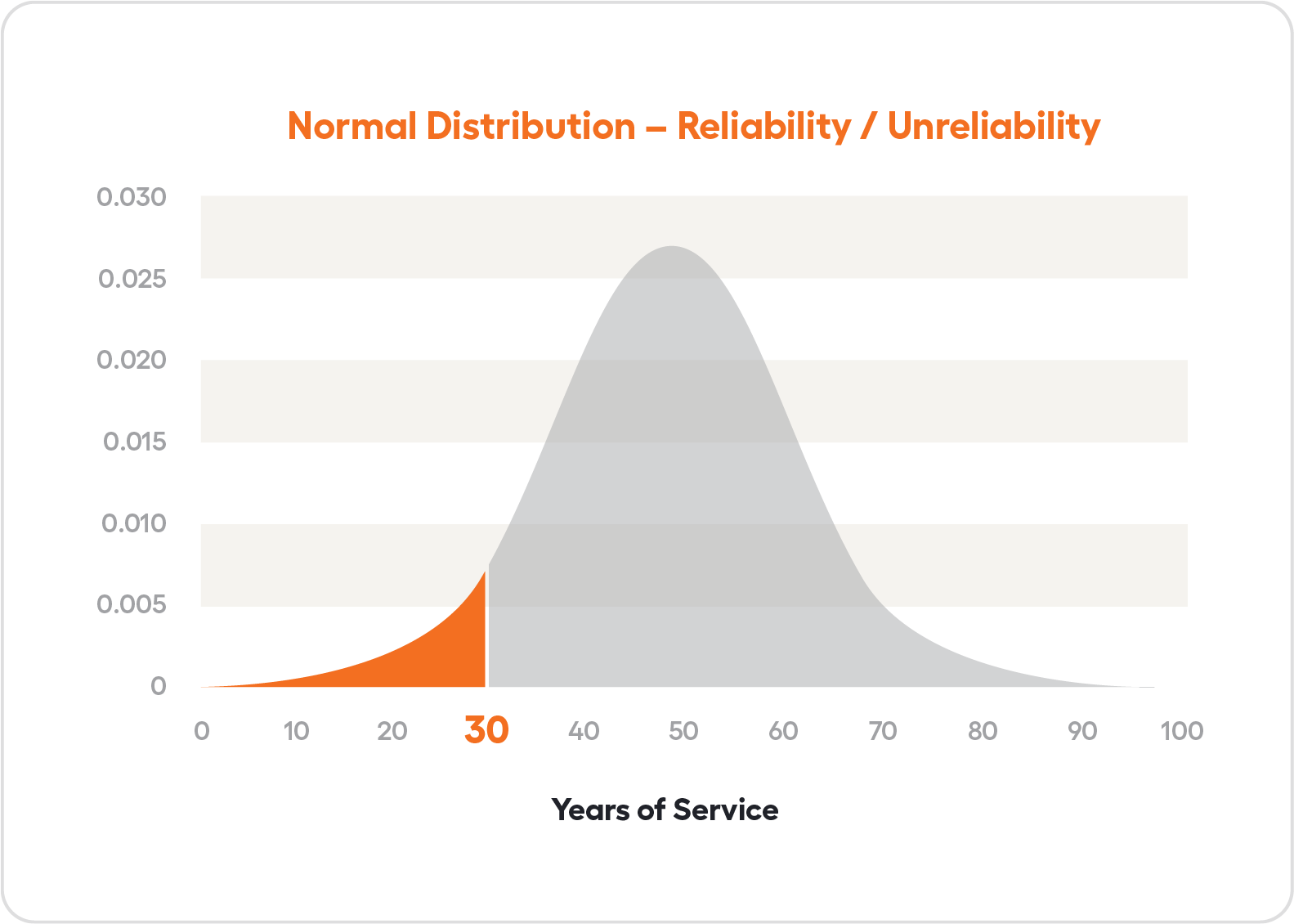
That is, the percentage of grounding conductors that are not expected to survive in the field are represented in Figure 2 by the area under the bell curve from Year 0 to Year 30 highlighted in orange.
What is the unreliability, Q(t), of a copper grounding wire? And what causes it?
A number of issues contribute to grounding failures in the field. An incomplete ground path is created by one of the following: theft (A), corrosion (B), loose connectors (C), or breakage (D). Limiting our consideration to these four major issues, a probability of failure can be estimated for each. And the sum of the probabilities of failure provides the unreliability, Q(t).
So that,
Q(t) = P (A) + P (B) + P (C) + P (D)
where,
P (A) = Probability of a broken circuit due to conductor theft
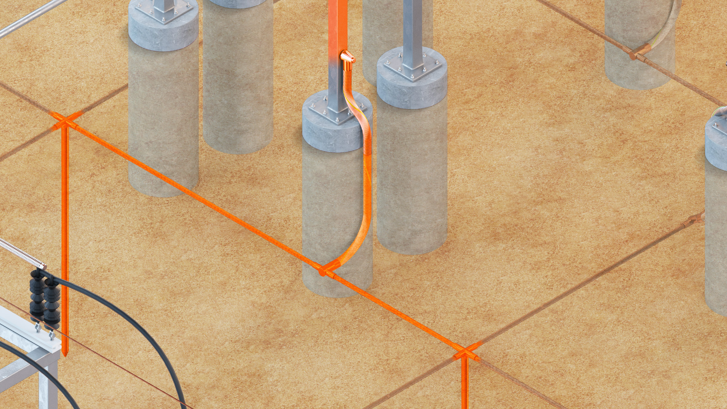
Transformers and tower legs are often targeted. The most vulnerable section of our power grid is from the ground level to about six feet up. Some sophisticated thieves even venture into the substation for above-grade copper ground connections, increasing the threat from step-and-touch potential.
P (B) = probability of a broken circuit due to conductor corrosion
Copper is naturally corrosion-resistant. As the surface oxidizes, it protects the conductor from further deterioration. Properly manufactured copper-covered steel and acceptance criteria are specified in per ASTM-B910, the standard for CCS wire construction. 6
P (C) = probability of a broken circuit due to loose conductor connectors
Solid copper pole grounding wires can soften, elongate, and loosen under their connectors from periodic short circuit loading. The same is true of copper inside any other connector, such as connectors at the overhead neutral, especially hard drawn copper wire.
P (D) = probability of a broken circuit due to conductor breaks
Expanding the footprint of existing substations leaves connections vulnerable to “frost heaving” of disturbed soils. Vibration of pigtail connections in the air causes wind fatigue over the service life of the substation.
Unfortunately, the body of evidence supporting an absolute value for each of the needed probabilities of failure for standard copper is limited.
Standards engineers working for Investor-owned and public utilities can provide anecdotal evidence for the probability of failures in the form of customer testimonials from the field, often provided by the linemen who work with the material every day. Similarly, manufacturers can provide evidence for utilities who explore technologies to ‘harden’ their areas of the power grid based on such testimonials. This is the case with CCS, too. However, measuring the probability of failure is a challenge.
Given the lack of available failure rates, a better method for predicting failure in the field may be by relative comparison. In some cases, the body of evidence supporting absolute probabilities can be circumvented by using Subject Matter Expert (SME) testimony. The unreliability of various grounding conductors can be compared by considering a number of known issues that cause grounding conductors to fail in the field.
The SME is a person who has special knowledge, skills, or abilities related to a particular work task or topic. SMEs can be used to extract intelligence from complex operations when developing educational programs. When harnessed correctly, the knowledge gained from SMEs has been used to design revolutionary human-in-the-loop control rooms and other complex integrated systems. 7
Reliability can be determined from a comparative scoring method using SME surveys. For each grounding conductor type, an estimated probability can be assigned relative to something else, rather than basing reliability on absolute numbers collected from field data. For example, the failure of CCS can be scored relative to existing copper in place throughout the power grid.
In sessions conducted in 2018 and 2019, four grounding SMEs with over 100 years of combined conductor selection experience, representing 1 million packages (large wooden reels and small plastic spools, combined) of CCS sold into the Power Grid market over a 10-year period from 2008 to 2019, were asked a series of questions about reliability issues in the field. Scores were recorded for the likelihood of failure cause by each issue for copper versus CCS, over an assumed service life of 30 years. Questions were asked to each SME separately, scoring standard copper first to establish baseline performance. Then the SME was asked to consider the same question for CCS separately. Finally, each SME was asked to make any adjustments to any of the values after seeing the results provided side by side.
The SME survey results yielded a score for Q(t)1, the relative unreliability of conductor 1 with respect to conductor 2, and vice versa.
So that,
Q(t)1 = P (A1) + P(B1) + P(C1) + P(D1)
Q(t)2 = P (A2) + P(B2) + P(C2) + P(D2)
Where,
Q(t)1 is the unreliability of copper
Q(t)2 is the unreliability of CCS, with respect to copper
P(A) of Theft – the probability of theft of copper over a 30-year life is estimated to be 5%, whereas the comparable probability of theft of CCS is 0.5%.
P (A1) = 0.10 for copper
P (A2) = 0.005 for CCS
P(B) of Corrosion – the probability of corrosion of copper over a 30-year life is 1%, whereas the comparable probability of theft of CCS is the same 1%.
P (B1) = 0.01 for copper
P (B2) = 0.01 for CCS
P(C) of Loosening – the probability of loosening at the connectors for copper over a 30-year life is 2%, whereas the comparable probability of theft of CCS is 1%.
P (C1) = 0.02 for copper
P (C2) = 0.01 for CCS
P(D) of Breaking – the probability of breakage for copper over a 30-year life is 5%, whereas the comparable probability of theft of CCS is 1%.
P (D1) = 0.05 for CCS
P (D2) = 0.01 for CCS
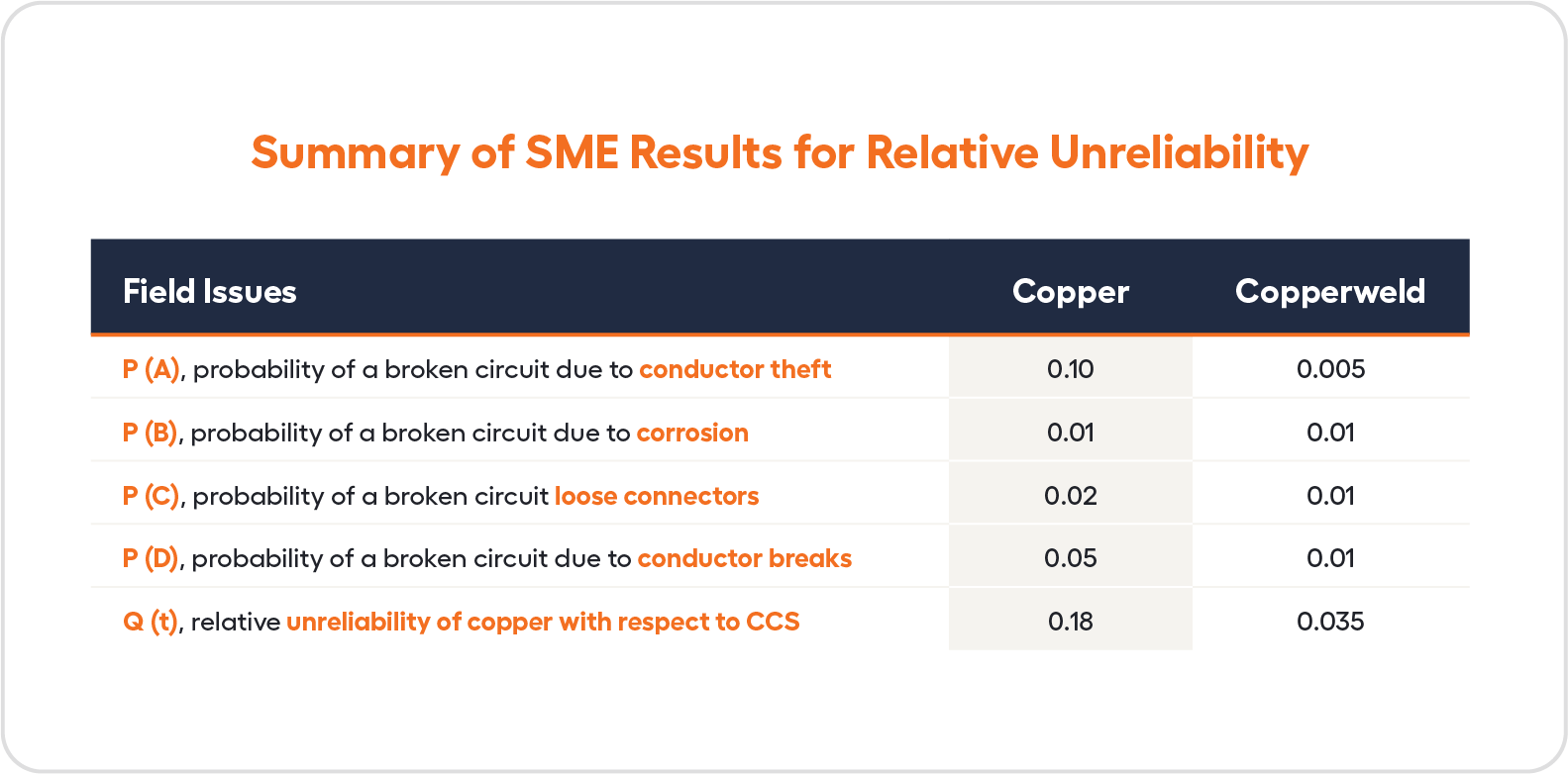
Unreliability of Copper: 0.10 + 0.01 + 0.02 + 0.05 = 0.18
Unreliability of CCS: 0.005 + 0.01 + 0.01 + 0.01 = 0.035, or rounded to 0.04
Given, the reliability of standard copper grounding conductors over a 30-year service life is 0.82, or 82%. The reliability of CCS grounding conductors over a 30-year service life, with respect to the standard copper grounding solutions, is 0.96, or 96%. According to SMEs, the failure rate of a copper ground path is 4x worse than the CCS alternative.
Utilities are actively searching for more resilient solutions. In the context of reliability, the improvement identified for CCS over the standard copper solution is its Resiliency.
Copper is the baseline, the point of comparison. So, it is the denominator of our reliability improvement calculation. In other words, we are comparing to the standard reliability of copper, which is 82%. Using the percent change, (b-a)/bx100 to determine resiliency over copper.
Resiliency = (.96-.82) / .82
Resiliency = .14 / .82
Resiliency = .17
Resiliency = 17%
A visualization of this resulting value resiliency comparison is provided in Figure 3. For CCS, the predicted failure rate at 30 years of installed service is significantly lower, according to SME testimony. By the percent change formula, a resiliency comparison at 30 years reveals that CCS is 17% more reliable.
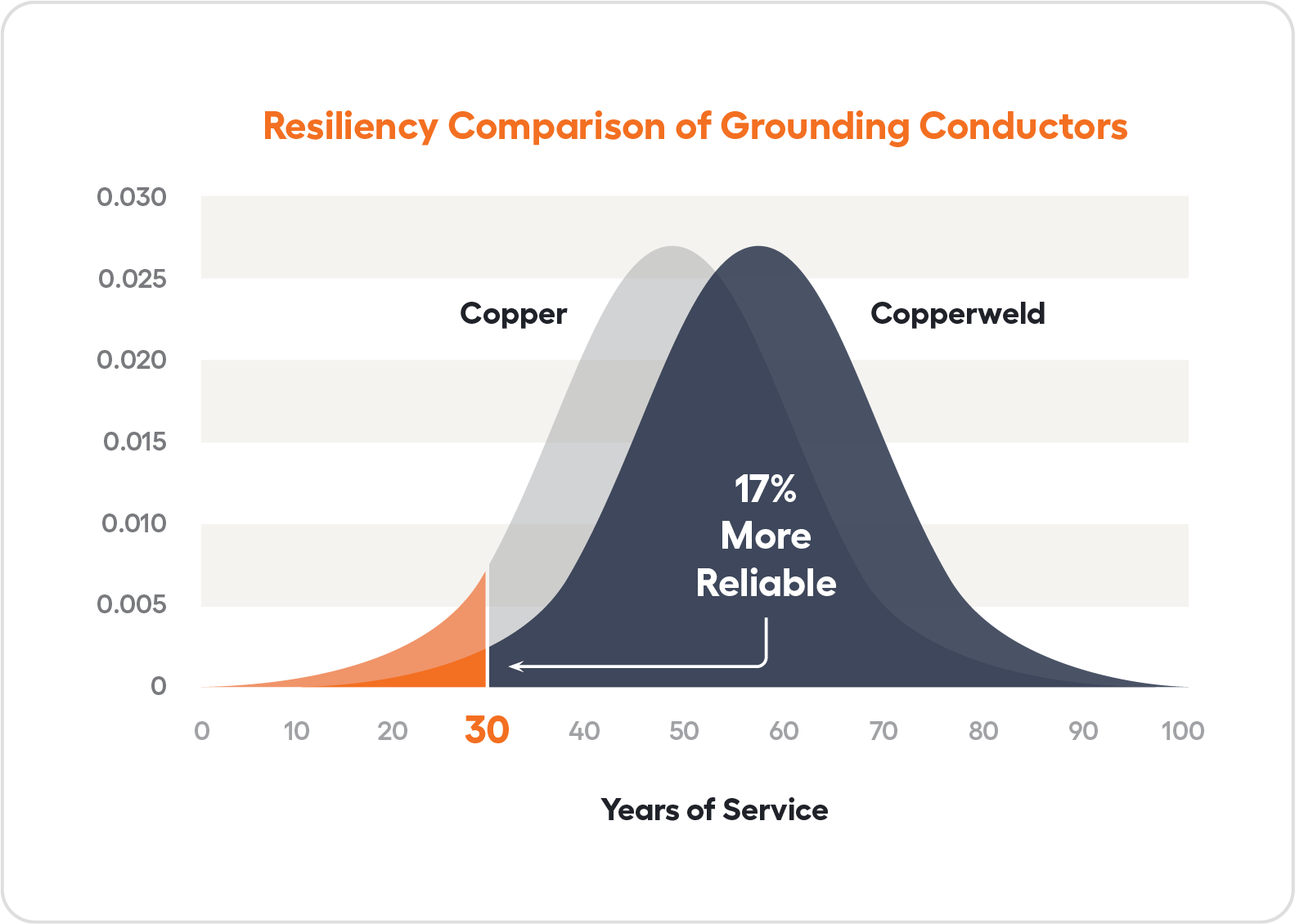
Using SME testimony and a new method to score potential modes of failure, a resiliency comparison at 30 years reveals that CCS is 17% more reliable in grounding applications than standard copper solutions.
This reliability improvement for CCS over copper takes into account the likelihood of ground wire breaks, loosening joints, theft, and wind fatigue. Further work is needed to verify the estimates provided by SME testimony by means of additional and wider surveys of community experts, or by collecting field data directly from visual inspections and continuity testing from the utilities, themselves.
Buried and above grade reliability performance was generalized in this initial work to help establish the new quantification method. No distinction was made for smaller gauge wires on power poles and larger gauge cables in-ground grids. Future work may divide performance into applications such as Distribution pole grounding, Substation ground grid, etc. in an attempt to account for specific differences in the reliability of buried versus above-grade grounding solutions.
The Relative Unreliability quantification method presented in this paper could be used for comparison of other grounding conductor materials.
Copperweld's friendly sales team is ready to fill your order or help you select products to deliver the performance you need.
Follow us on your favorite social platforms:


Sign up for Copperweld news to learn about the latest industry updates, events, product releases, videos and technical documents.